
Tasmota RF Bridge
|
Tasmota RF Bridge
A simple project: A Tasmota based 433MHz RF bridge,
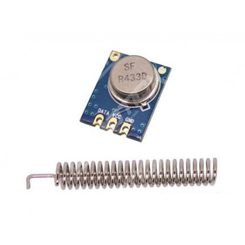
Components:
Installation
The first step was to reflash the NodeMCU with the latest version of Tasmota Sensors. This is as easy as connecting the NodeMCU via a USB cable to the PC, and visit the Tasmota Install page with the Chrome browser (note: Firefox won’t work).
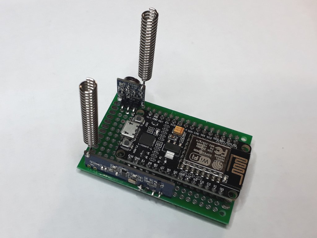
The NodeMCU mounted on a PCB board, with the receiver and transmitter.
The receiver has 4 connections: Vcc, CS, Data and Ground. CS must be connected to Vcc for normal working mode.
The transmitter has 3 connections: Vcc, Data and Ground.
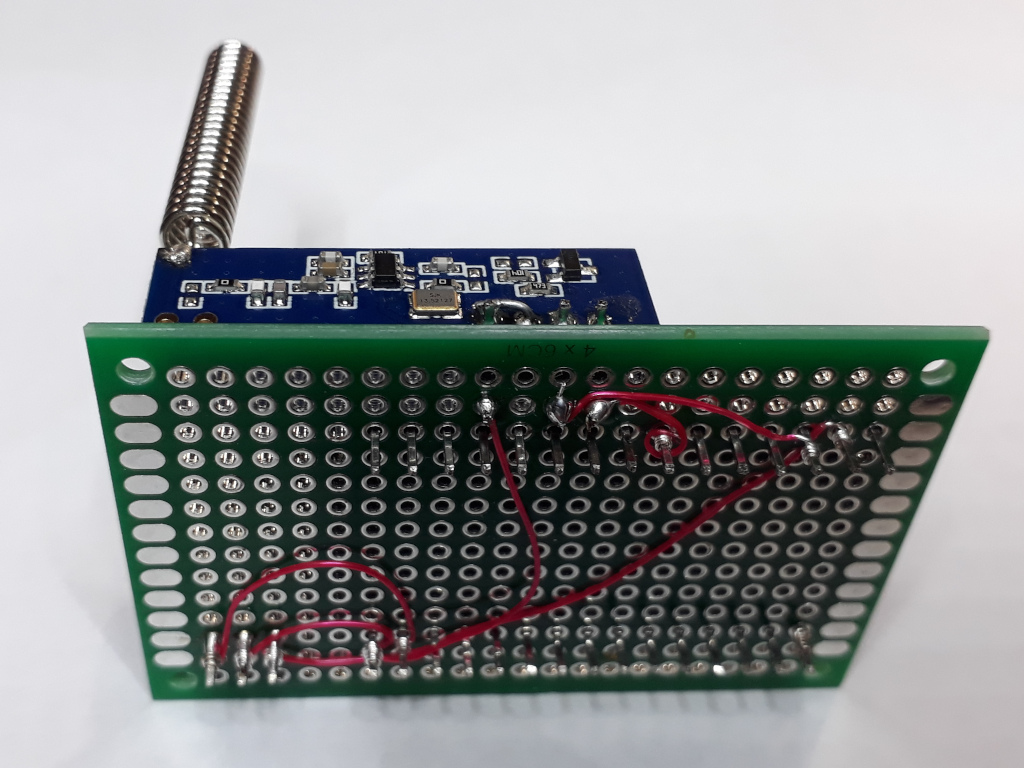
I remembered just in time that I bought a wire-wrap tool some time ago (in 1979).
I used it a couple of times to rewire a Digital PDP-11 serial port from 1200 to a whopping 9600 baud.
Configuring Tasmota
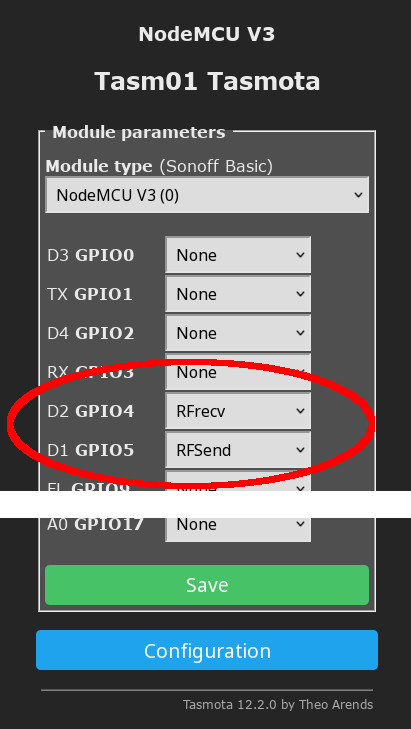
The transmitter data goes to D1 (GPIO5) and the receiver data goes to D2 (GIO4).
When a signal is received, Tasmota sends an MQTT message to topic
tele/tasm01/RESULT similar to
{"Time":"2022-11-04T14:16:07","RfReceived":{"Data":"0xXXXXXX","Bits":24,"Protocol":17,"Pulse":500}}
Home Assistant
In Home Assistant I added a sensor RfBridge Signal by
publishing the appropriate config to MQTT autodiscovery:
            {
               "name" : "RfBridge Signal",
               "unique_id" : "rfbridge_signal",
               "~" : "tele/tasm01",
               "state_topic" : "~/RESULT",
               "value_template" : "{{ value_json.RfReceived.Data }}",
               "json_attributes_topic" : "~/RESULT",
               "availability" : [
                  {
                     "payload_available" : "Online",
                     "payload_not_available" : "Offline",
                     "topic" : "~/LWT"
                  }
               ],
               "device" : {
                  "identifiers" : [
                     "Tasm01"
                  ],
                  "manufacturer" : "Tasmota",
                  "model" : "NodeMCU",
                  "name" : "RfBridge",
                  "sw_version" : "12.2.0"
               },
            }
By publishing this message to MQTT topic
homeassistant/sensor/rfbridge/signal/config HA will add a
MQTT device RfBridge with one sensor.
In the Developers Tools we can see that the full content of the MQTT message is passed as attributes to Signal. That’s what the "json_attributes_topic" : "~/RESULT" does.
Now we can define a simple trigger for when a signal is received.
automation:
  - id: Automation__RfBridge_Button_Pressed
    alias: RfBridge Button Pressed
    mode: queued

    trigger:
      - platform: state
        entity_id:
        - sensor.rfbridge_signal

    action:
      - service: telegram_bot.send_message
        data:
          message: "Button {{ trigger.to_state.state }} pressed"
While this works, it is too simple.
Home Assistant triggers respond to state changes. So when a button is pressed and then pressed again, the second press will not fire the trigger. The state, which is the button code, does not change.
Likewise, when the bridge would go offline and then
reconnects, which seem to happen in practice, the state shortly goes
to Unavailable and is then restored to the old value.
This is a state change so the trigger is fired.
To overcome this we will make the trigger fire on a change of the timestamp instead of the state. Also, we’ll add a condition to prevent accidental firing when there’s a short interruption.
automation:
  - id: Automation__RfBridge_Button_Pressed
    alias: RfBridge Button Pressed
    mode: queued

    trigger:
      - platform: state
        entity_id:
        - sensor.rfbridge_signal
        attribute: Time

    condition: |-
      {{ trigger.to_state.state not in ( "unavailable", "unknown" )
         and
         trigger.from_state.state != "unavailable"
      }}

    action:
      - service: telegram_bot.send_message
        data:
          message: "Button {{ trigger.to_state.state }} pressed"
Wrapping Up
The final configuration is a bit more complex. It defines some other sensors, mainly for diagnostics, and uses a dispatch table for known buttons (thanks, Ed for the suggestions!).
© Copyright 2003-2023 Johan Vromans. All Rights Reserved.
articles/tasmota_rfbridge/index.html last modified 16:05:02 04-Nov-2022